Buttressed cores, diagrid geometry and verified construction
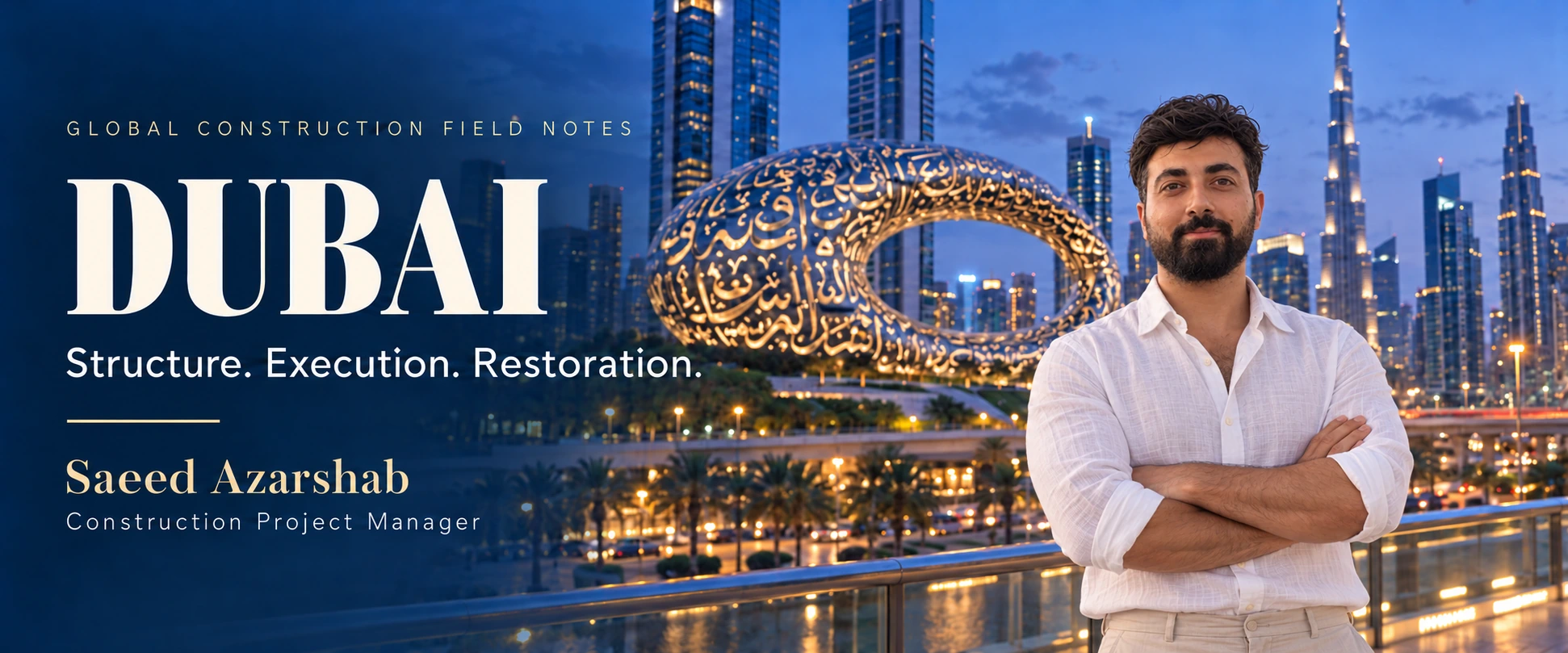
Dubai’s tower skyline, Museum of the Future and waterside public realm connect three delivery questions: vertical logistics, non-repetitive geometry and operation in a demanding climate. I use the images to make those questions tangible, while distinguishing visible form from the hidden core, foundations, diagrid nodes and measured environmental performance.
I would connect design geometry to fabrication identification, site survey and envelope acceptance, then to maintenance access and commissioning. The visually ambitious surface should not become a reason to accept unclear tolerances or inaccessible details; the value of digital information is the construction decision it supports.
Part 1 of 2
Start with the load path
A very tall concrete tower and a low-rise steel diagrid present different construction problems. They need different supply chains, erection methods and tolerance strategies. I start by asking how gravity and lateral loads reach the ground, then how the structure remains stable at each stage. This makes a landmark useful as a construction case study: the visible form becomes connected to identifiable structural and delivery requirements.
Ground, water and exposure
For a project in Dubai, I would investigate the actual soil profile, groundwater chemistry and exposure conditions before selecting foundation and durability details. Chlorides can contribute to reinforcement corrosion where they reach susceptible steel. Concrete permeability, cover, crack control, curing and protective measures therefore need coordinated attention. I would assign exposure conditions to the relevant components rather than assume that every Dubai site has the same groundwater or that all parts of a building experience the same environment.
Burj Khalifa: a buttressed-core system
SOM describes Burj Khalifa as an 828-metre reinforced-concrete tower with a central buttressed core. Its wings contribute to the structural system, while the changing profile relates to wind response. I read it as a coordinated form rather than a stack of independent floors. The conceptual diagram isolates the central core, buttressing wings and floor relationships; it does not reproduce the tower's actual member dimensions or reinforcement. [1]
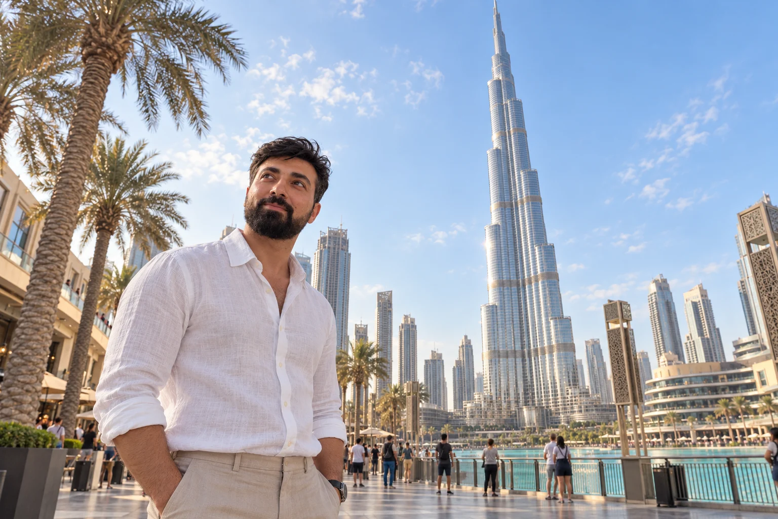
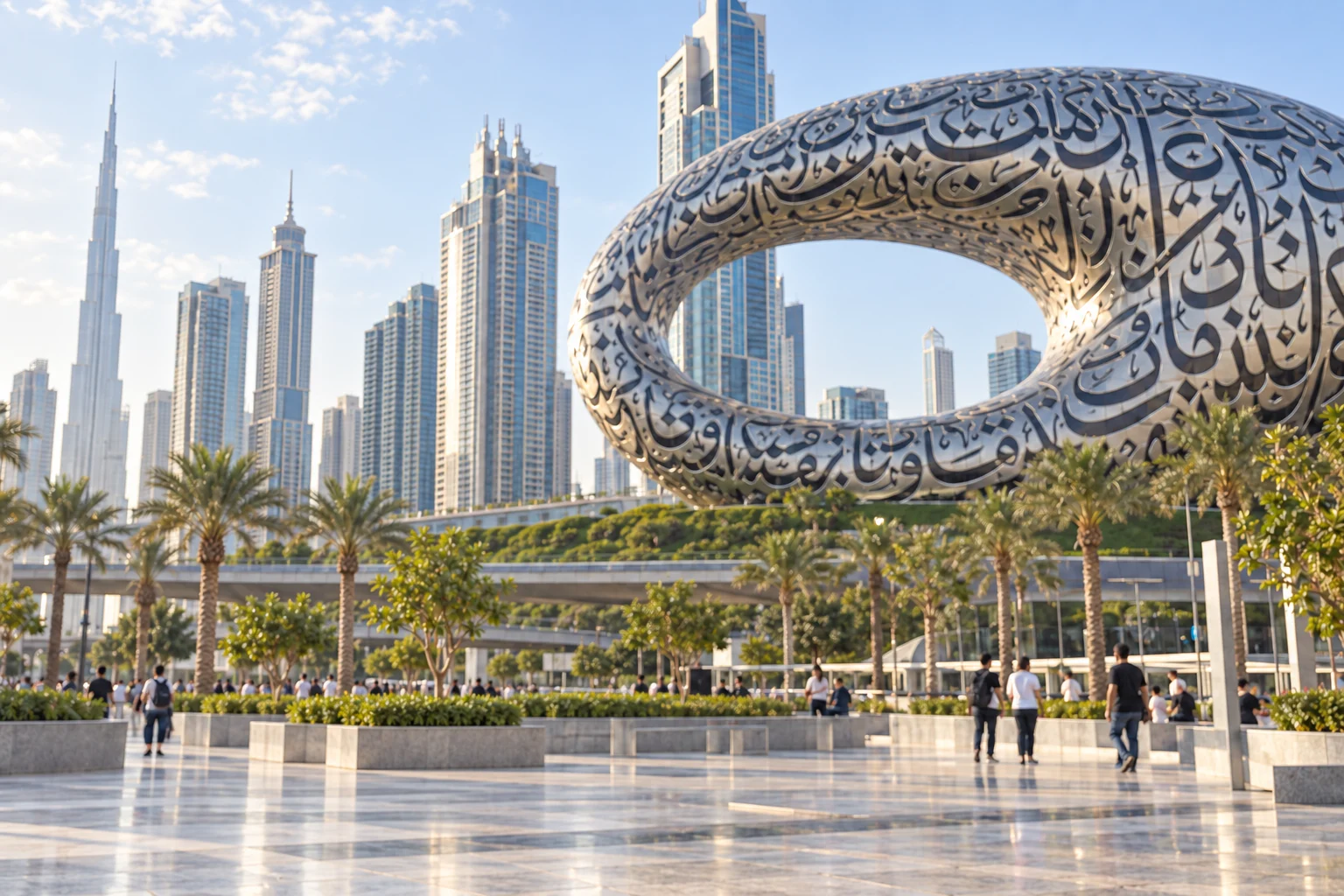
Burj Khalifa setting — the tapering skyline profile introduces tower form and vertical delivery; the core and foundation system are established by the project sources.
A foundation that connects structure and durability
The tower's official structural account identifies a reinforced-concrete mat supported on bored reinforced-concrete piles, and low-permeability concrete in the foundation description. The lesson for me is that geotechnical performance and material protection belong in the same project conversation. An imposing superstructure rests on less visible decisions about investigation, foundation construction, quality control and long-term exposure. [2]
Vertical logistics and acceptance
I would coordinate formwork cycles, concrete delivery, survey control, temporary access and material handling with the evolving frame. Services create another set of vertical dependencies through risers, plant spaces and commissioning zones. Production rhythm is useful when it supports whole-building completion. My visit sharpened my interest in how construction sequencing and inspection can keep that rhythm connected to a functioning asset.
Part 2 of 2
Museum of the Future: geometry changes the problem
Leica Geosystems' project account describes a steel diagrid formed from approximately 2,400 intersecting members, with Killa Design as architect and Buro Happold responsible for the parametric structural design. This is a different structural category from the buttressed-core tower. Its value for me is the link between non-repetitive geometry, fabrication accuracy and erection planning: a successful local connection depends on its position within the larger coordinated form. [3]
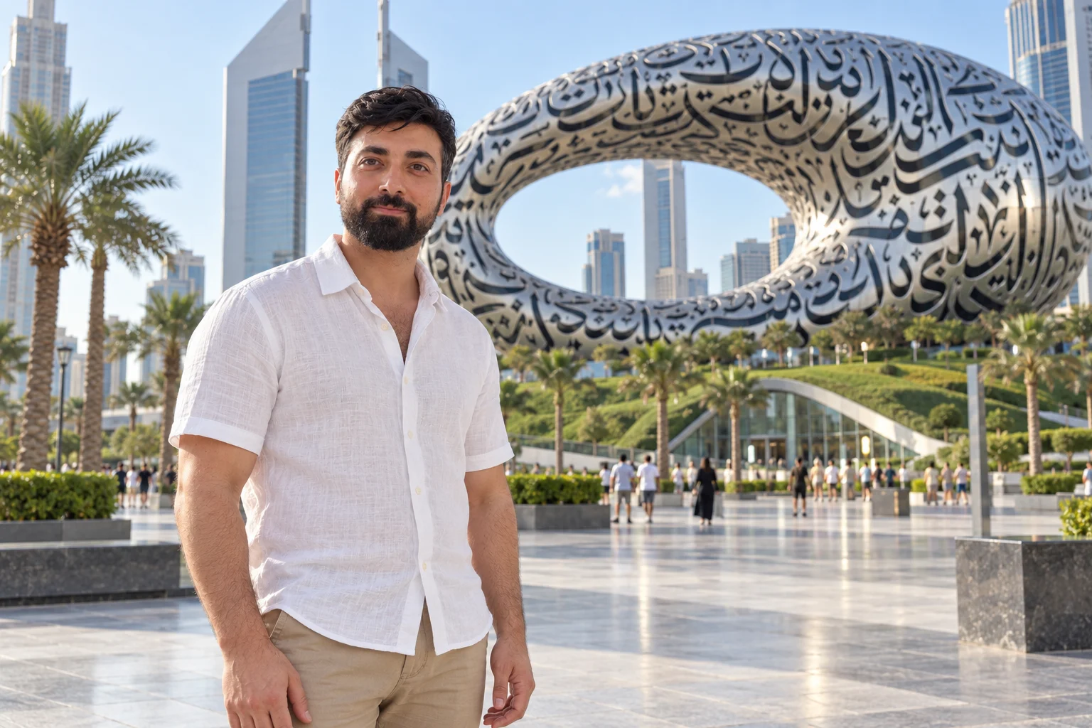
Museum of the Future exterior — the patterned envelope introduces the frame-to-skin interface and geometric verification, not an exposed view of the diagrid connections.Museum of the Future — the opening and continuous curved surface make non-repetitive geometry visible, while the structural nodes sit behind the envelope.
Survey evidence closes the loop
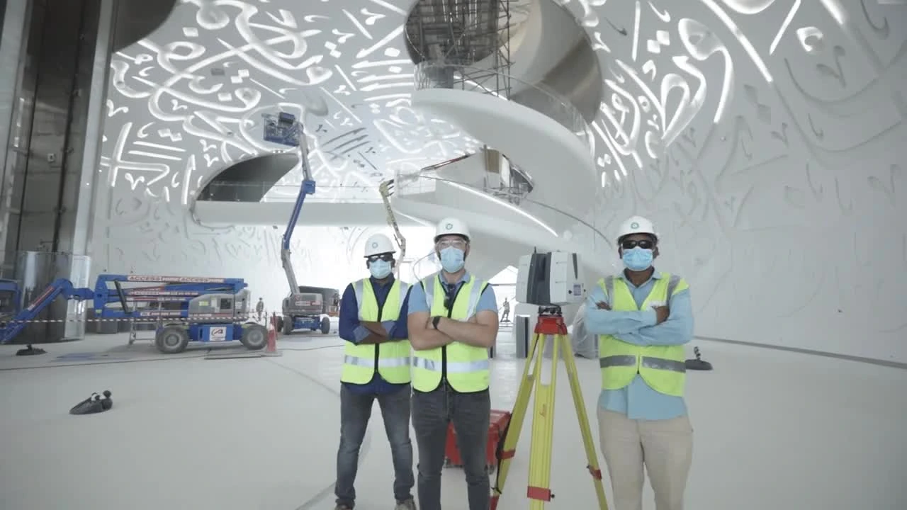
The same account describes BAM's use of laser scanning to check manufactured and installed geometry and coordinate with fabricators. I would connect a detected discrepancy to an agreed tolerance, a responsible party and a decision about adjustment or rework. A detailed point cloud becomes useful when it answers a construction question. The relationship between design geometry and installed geometry needs verification throughout the assembly, rather than only at final handover. [3]
The frame-to-envelope interface
Diagrid nodes, facade brackets, service penetrations and lifting arrangements need coordinated details. I would control component identification, installation order and survey hold points so that a local error does not propagate through later work. Temporary restraint must be checked before the complete frame is available. The second Dubai study shows a generic diagrid assembly and its interfaces; the museum's actual toroidal geometry requires its own engineering information.
Climate and infrastructure are part of the brief
Solar exposure, dust and outdoor conditions influence envelope, cooling and maintenance requirements. At district scale, the building connects to energy, water, drainage and transport arrangements. I would evaluate environmental performance through design assumptions, commissioning and measured operation. A distinctive form or a label alone cannot answer how the building performs in use. Maintenance access needs to be integrated into the design of complex surfaces and connections.
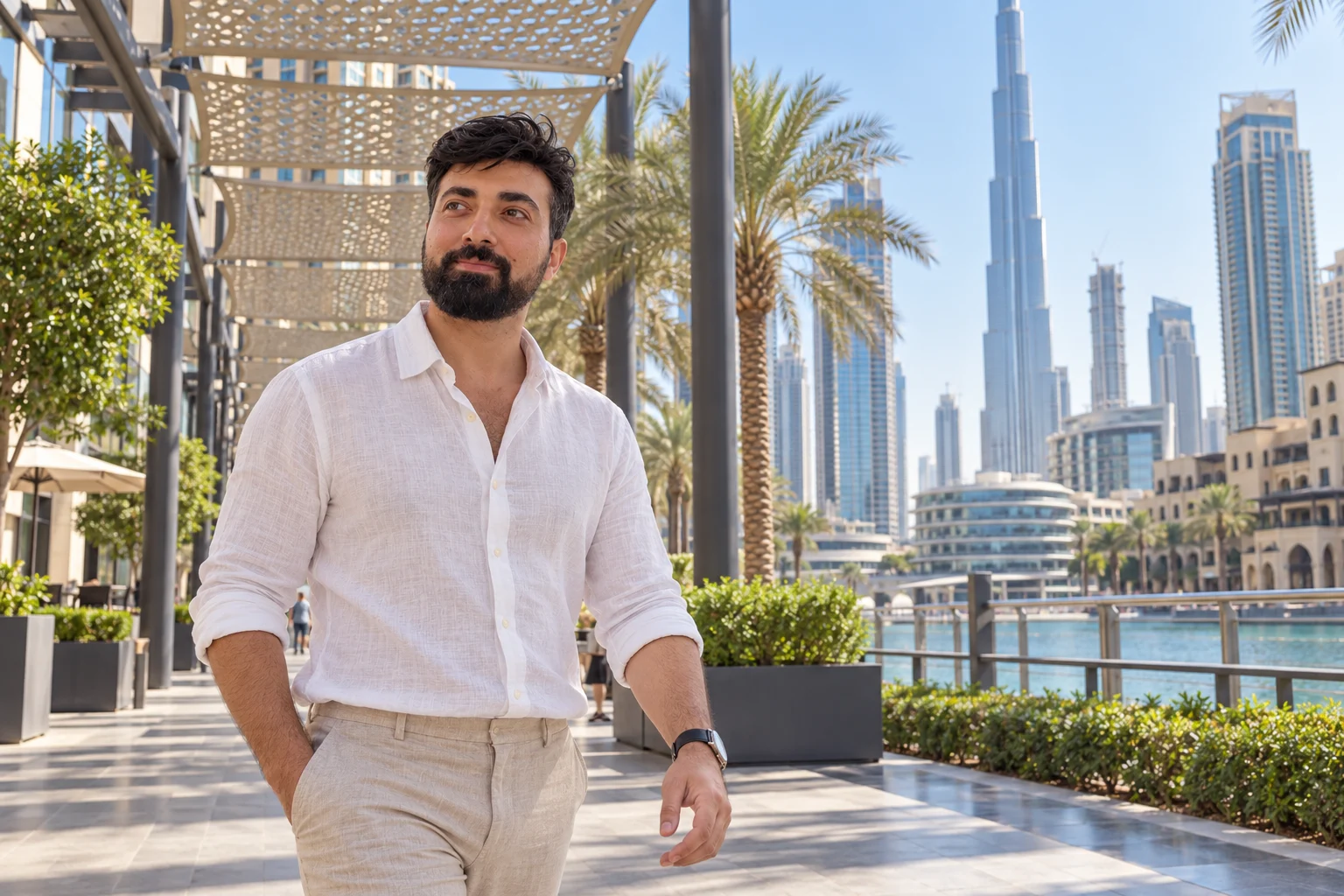
Dubai waterside public realm — shade structures, planting and surrounding towers connect climate, access and maintenance to the building brief; performance needs measured evidence.
My professional lesson from Dubai
Dubai strengthened my interest in verified buildability. An ambitious design needs a method for translating geometry into procurement, fabrication, installation and operating records. I favour a delivery process in which the coordinated model, programme and survey evidence remain connected. The outcome I value is a functioning and maintainable asset, with a clear load path and a traceable construction history.
3D construction studies
Buttressed-core principle
Structural assembly. Conceptual 3D teaching model; not surveyed geometry or a construction instruction.02 · Construction sequence overview. Follow stages 01–05 below; the same axonometric model is retained throughout.
Five fixed-camera views. Stages illustrate construction relationships; project activities can overlap. Independent SVG/PNG frames and an animated sequence are supplied in the asset package.
Loads and interfaces. Conceptual 3D teaching model; not surveyed geometry or a construction instruction.
Diagrid geometry and survey control
Structural assembly. Conceptual 3D teaching model; not surveyed geometry or a construction instruction.02 · Construction sequence overview. Follow stages 01–05 below; the same axonometric model is retained throughout.
Five fixed-camera views. Stages illustrate construction relationships; project activities can overlap. Independent SVG/PNG frames and an animated sequence are supplied in the asset package.
Loads and interfaces. Conceptual 3D teaching model; not surveyed geometry or a construction instruction.
Real project photographs and archive material
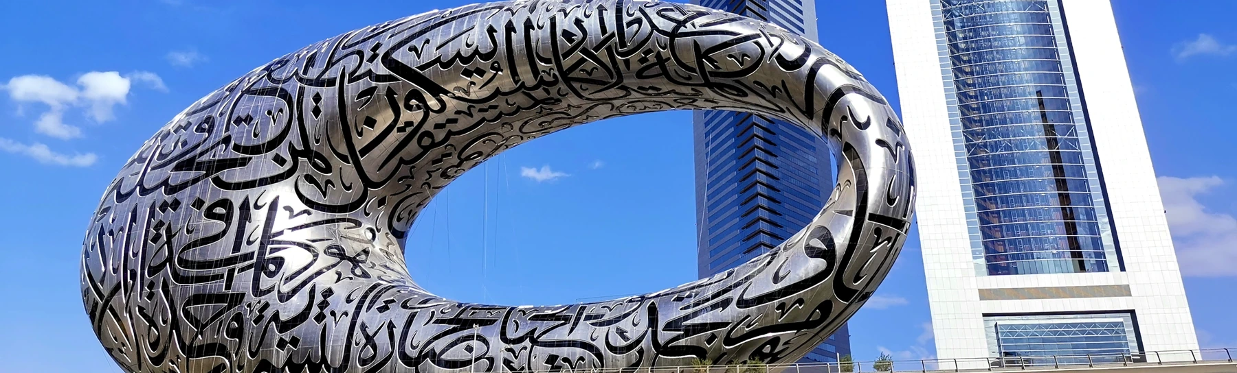
Completed buildingMuseum of the Future: completed exterior
Capture date not supplied by retrieved source · Native master: 2,480 × 750 px
Source: Leica Geosystems; photographer not identified in retrieved caption
Native source bytes retained; no upscaling or generative alteration.
Source and attribution ↗Video preview stillMuseum of the Future: survey team in the project video preview
Capture date not supplied by retrieved source · Native master: 1,280 × 720 px
Source: Leica Geosystems; photographer not identified in retrieved caption
Native source bytes retained; no upscaling or generative alteration. This is the source page’s video preview, not a separately dated construction photograph.
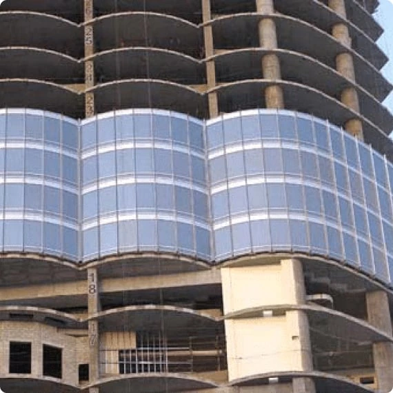
Source and attribution ↗Construction / installation archiveBurj Khalifa: facade and exposed floors in the official structure archive
Capture date not supplied by retrieved source · Native master: 570 × 570 px
Source: Burj Khalifa / Emaar; photographer not identified in retrieved caption
Native source bytes retained; no upscaling or generative alteration. Limited-resolution source: use as a supporting image, not a full-screen hero.
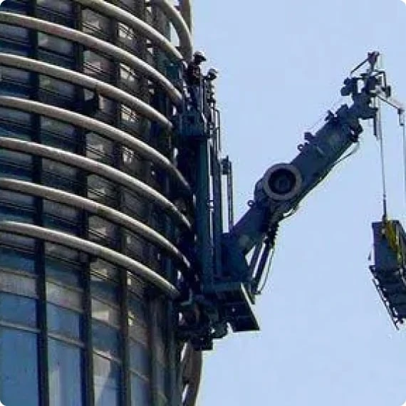
Source and attribution ↗Building access referenceBurj Khalifa: facade-access equipment in the official structure archive
Capture date not supplied by retrieved source · Native master: 570 × 570 px
Source: Burj Khalifa / Emaar; photographer not identified in retrieved caption
Native source bytes retained; no upscaling or generative alteration. Limited-resolution source: use as a supporting image, not a full-screen hero.
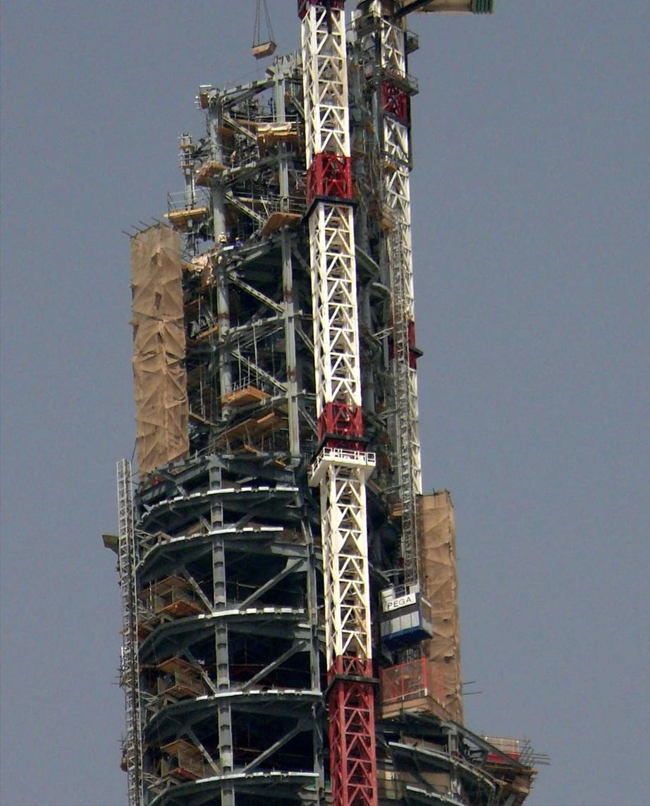
Source and attribution ↗ConstructionBurj Khalifa upper structure under construction, 25 June 2008
25 June 2008 - capture date identified by source · Native master: 922 × 1,143 px
Imre Solt / Wikimedia Commons - CC BY-SA 3.0
Original 922 × 1,143 px archive retained. Web derivative re-encoded only; no upscaling. Licence: https://creativecommons.org/licenses/by-sa/3.0/