Six structural case studies: movement, prefabrication, folded surfaces and recovery
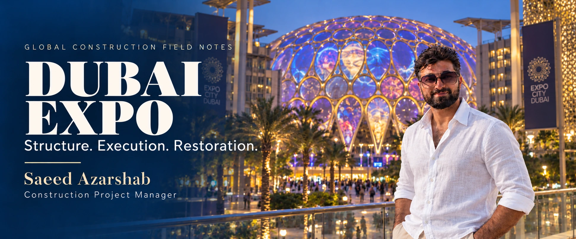
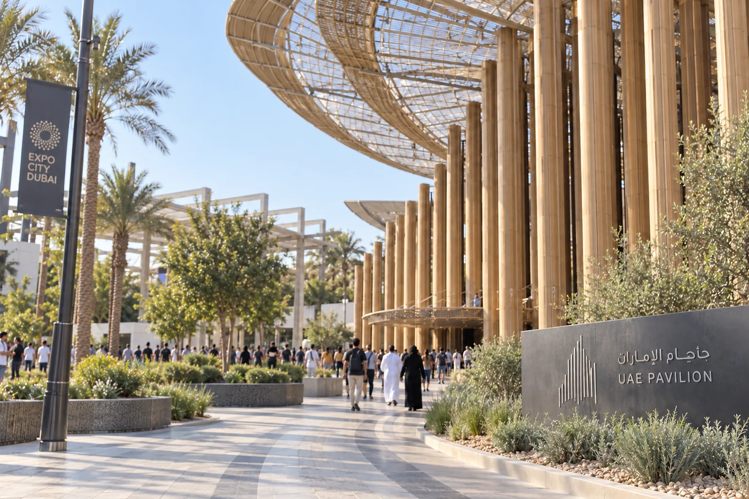
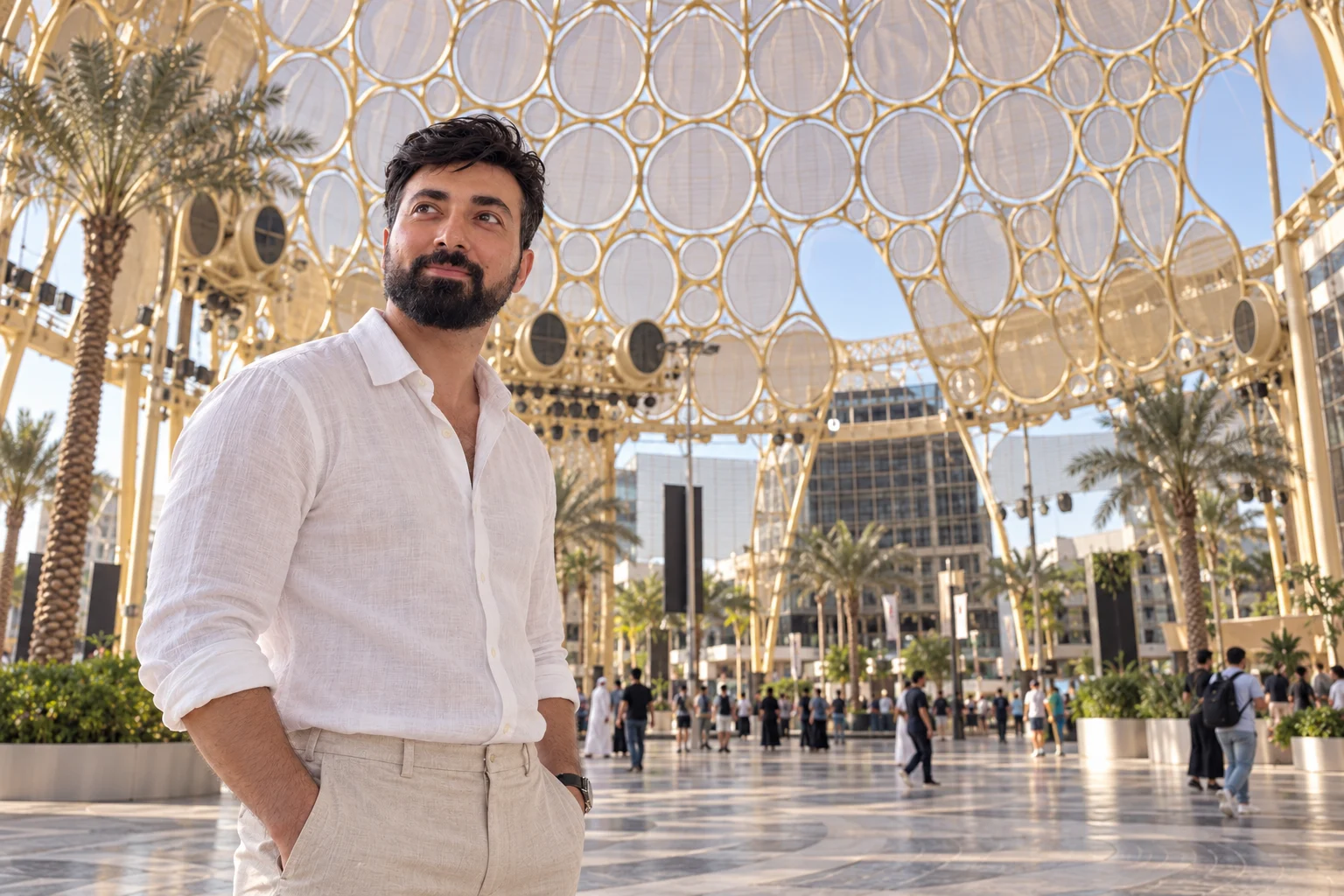
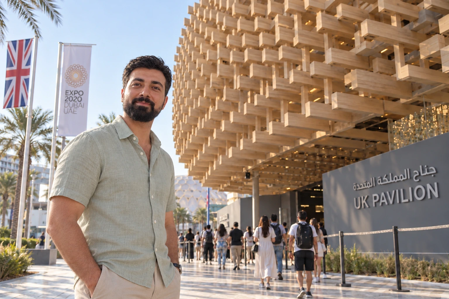
The selected Expo images establish the visitor setting and show the contrasting assembly language of the UAE and UK pavilions. This study concerns Expo 2020 Dubai, held from 1 October 2021 to 31 March 2022. I extend the visual comparison to six documented national-pavilion case studies, distinguishing visible surfaces from the supporting systems, installation methods and recovery strategies described by their project teams. [1]
For temporary pavilions, I would plan erection and recovery together: identify components, verify stable incomplete stages, keep connections accessible and record receiving uses. A repeated visual pattern can conceal non-repeated geometry; a stated reuse ambition needs ownership, inspection and handling arrangements to become deliverable.
Structural comparison
Pavilion
Primary structural principle
Distinctive interface
Construction-management focus
Sources
United Arab Emirates
Concrete support + fixed steel roof
28 moving wings; roof solar panels
Hinge geometry, actuation and operation
[2]
United Kingdom
Timber cassettes + steel rings
Engineered-timber cone
Fabrication identification, erection restraint and recovery
[3, 4]
Japan
Freestanding folded frame
Triangular membranes on secondary supports
Frame stability, membrane tension and movement
[5]
Netherlands
Borrowed sheet piles + tubular struts
Concrete-free enclosure and climate exhibit
Recoverable support, accessible connections and receiving use
[6, 10]
Germany
Concrete cores + cube-wall steel trusses
Roof trusses and lightweight ETFE envelope
Staged stability and diaphragm completion
[7]
Saudi Arabia
Integrated permanent structure and facade
Mast-climber installation access
Temporary reactions, ties and installation dependencies
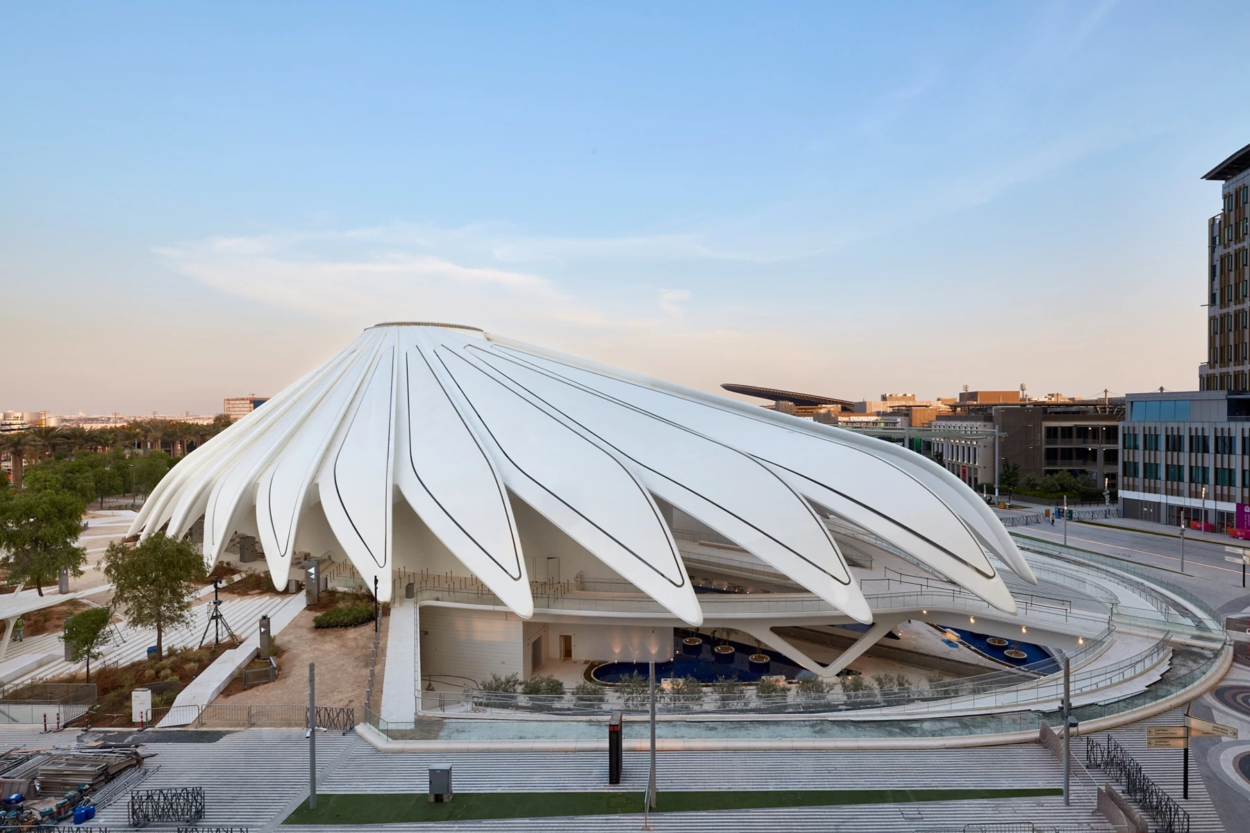
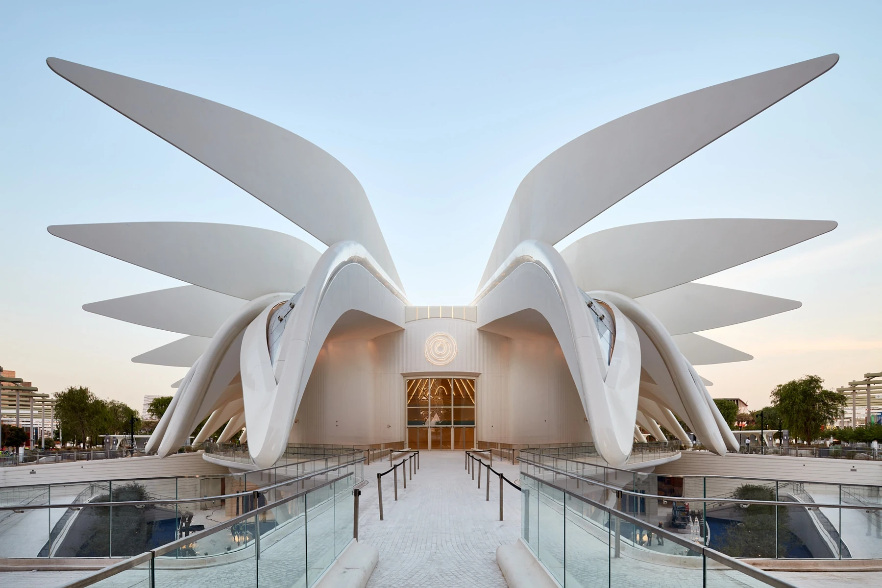
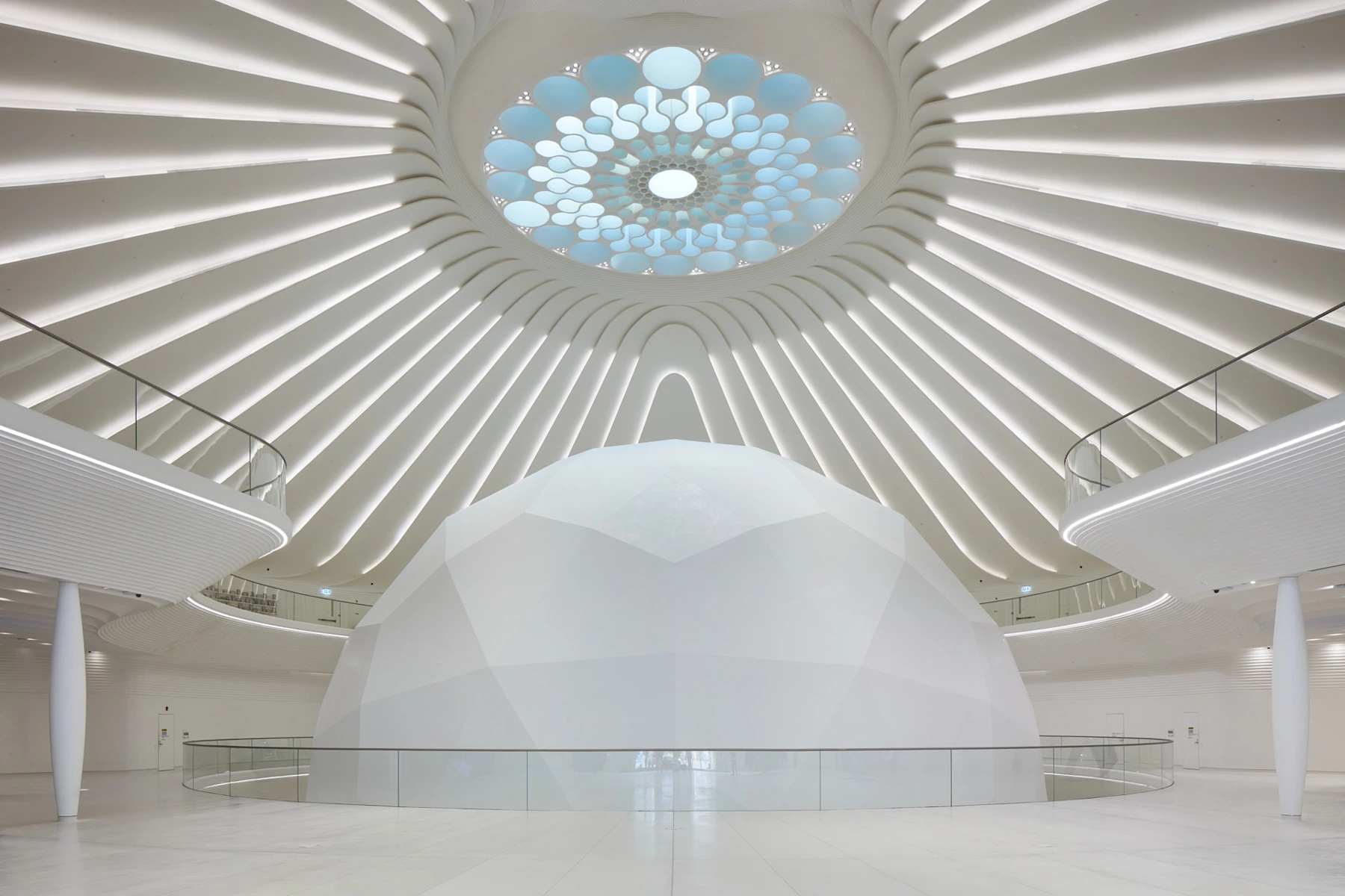
The BIE's Calatrava account identifies 28 movable wings above a pavilion combining concrete support and steel roofing. The curved concrete perimeter wall supports much of the exhibition-floor arrangement. The roof and the moving elements have different structural functions. I separate them when considering the load path: the feather-like appearance does not explain hinge forces, actuation requirements or the movement envelope. [2]
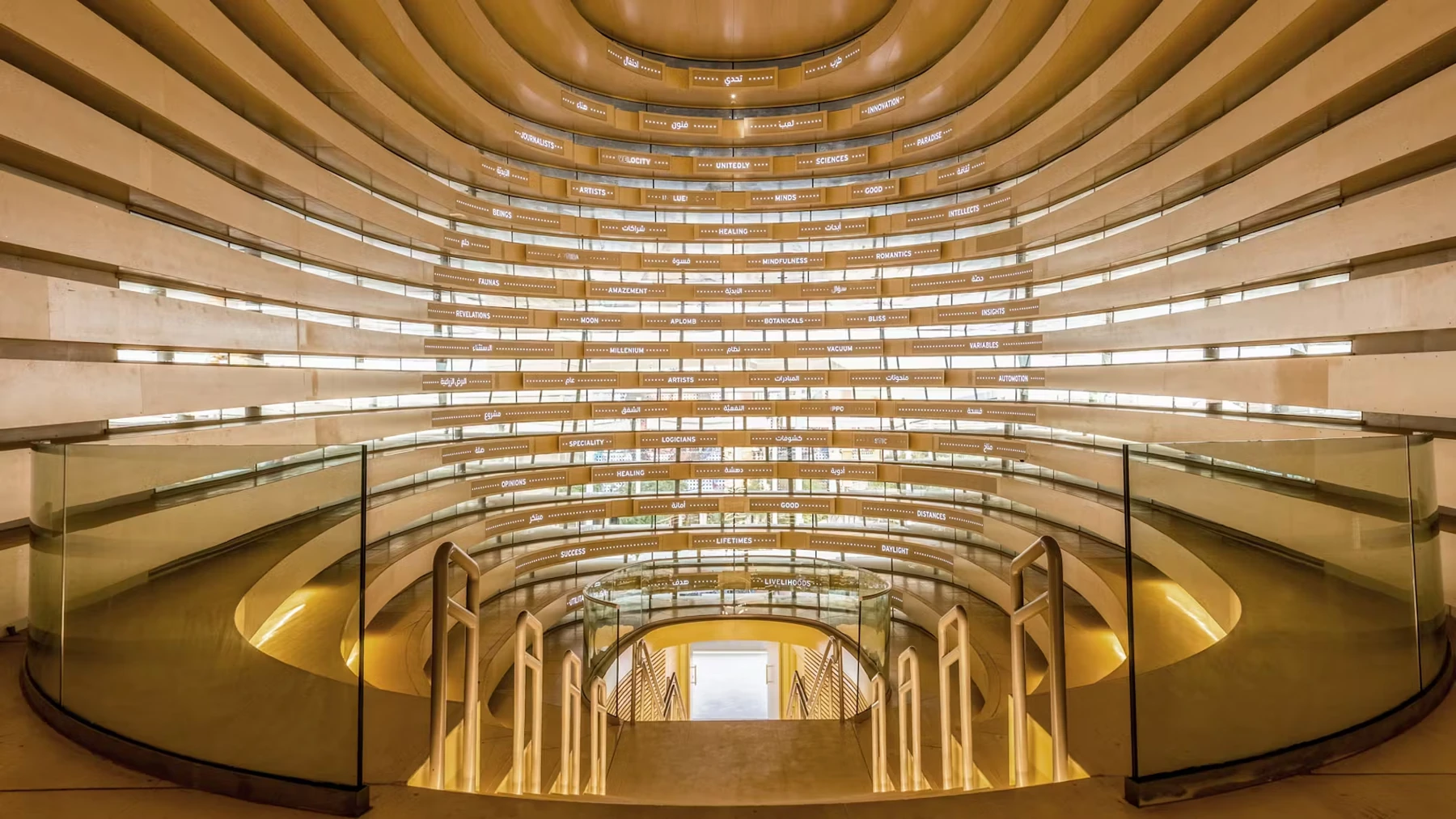
UAE pavilion — the rhythmic roof elements and visitor frontage introduce fixed and moving components; hinge behaviour and operation cannot be verified from a still view.Expo public realm — the patterned canopy and visitor space establish the exhibition setting; the six pavilion systems are compared through their separate project accounts.
Assembly and geometric control
My sequence uses a simplified roof-and-wing arrangement: concrete support, fixed steelwork, wing installation, movement-system connection and testing. I would treat roof geometry, hinge axes and actuator connections as coordinated control points. Survey checks are most useful while adjustment remains possible and before adjacent finishes restrict access. The model explains these relationships rather than reproducing the contractor's lifting sequence or the complete 28-wing geometry.
Structure, movement and electrical services
The BIE describes roof solar panels revealed by the moving wings. That creates interfaces between structural, mechanical and electrical packages. I would coordinate drainage, clearances, access and cable routing with the actual arrangement; the location of a solar panel does not establish that its wiring crosses a moving hinge. Commissioning needs agreed operating limits and fault responses, together with a maintenance strategy. [2]
What I take into my work
The pavilion illustrates a clear division of responsibilities within an expressive design. The fixed roof must remain structurally reliable while the wing system operates within verified limits. I would define inspection points and acceptance criteria before fabrication, and retain records for future maintenance. An architectural movement becomes a dependable asset through the interfaces that allow it to operate.
Fixed roof and moving wings
Structural assembly. Conceptual 3D teaching model; not surveyed geometry or a construction instruction.02 · Construction sequence overview. Follow stages 01–05 below; the same axonometric model is retained throughout.
Five fixed-camera views. Stages illustrate construction relationships; project activities can overlap. Independent SVG/PNG frames and an animated sequence are supplied in the asset package.
Loads and interfaces. Conceptual 3D teaching model; not surveyed geometry or a construction instruction.
Real project photographs and archive material
Completed buildingUAE pavilion: wings in the closed roof arrangement
Capture date not supplied by retrieved source · Native master: 1,920 × 1,280 px
Source: Santiago Calatrava; photographer not identified in retrieved caption
Native source bytes retained; no upscaling or generative alteration.
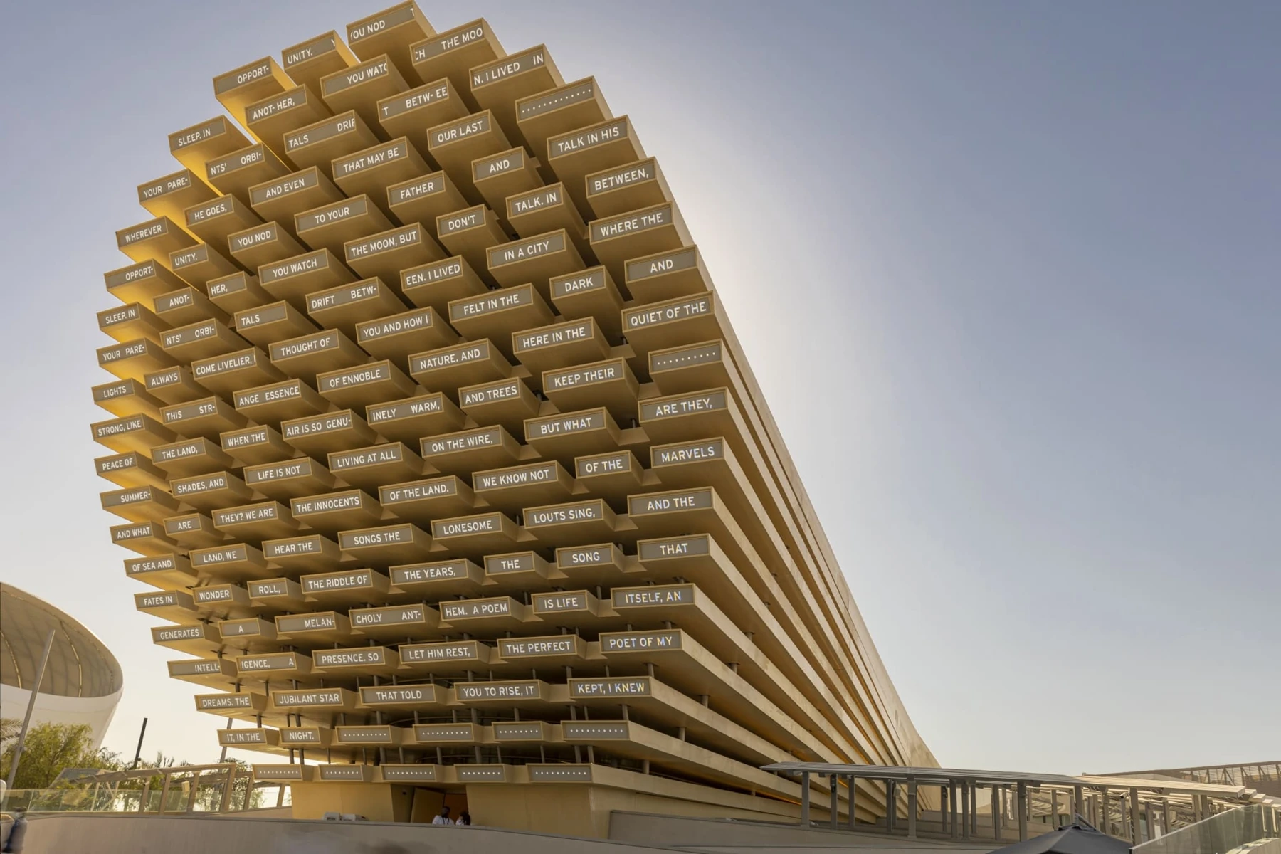
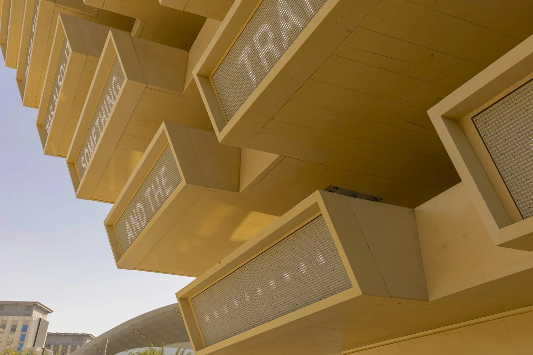
The Institution of Structural Engineers describes a demountable engineered-timber pavilion, structurally designed by Atelier One. Stacked timber cassettes and discreet steel rings create its hollow cone, with cross-laminated timber suited to CNC machining. McLaren describes substantial off-site manufacture and assembly. I see a link between digital geometry, repeatable fabrication and the accuracy needed to deliver the final form. [3, 4]
UK pavilion — projecting timber elements and the entrance show a visible assembly rhythm; supporting rings, connection details and restraint come from the engineering accounts.
A controlled route from workshop to site
My teaching sequence separates support preparation, cassette manufacture, steel-ring erection, cassette placement and completion. Real activities can overlap. Component identification and delivery order matter where geometries vary; lifting points, transport constraints and temporary restraint should be considered during design. Off-site manufacture changes the balance of site work, but assembly still needs stable temporary conditions and verified connection fit.
Connections and timber exposure
The timber-cassette and steel-ring relationship governs how local loads enter the supporting assembly. I would coordinate tolerances, fire requirements and material protection with the actual structural details. Timber also needs moisture management during transport, storage and use. The temporary exhibition brief does not remove those responsibilities, particularly where components are intended to remain useful after the event.
My project-management reading
I value the pavilion as an example of integrated production. Geometry has to connect to manufacturing capability, logistics and installation records. Repeatable joints can support efficient assembly even when the overall form is unusual. Demountability needs accessible connections and a reverse sequence; a short design life does not itself prove that recovery will be practical.
Timber cassettes and steel rings
Structural assembly. Conceptual 3D teaching model; not surveyed geometry or a construction instruction.02 · Construction sequence overview. Follow stages 01–05 below; the same axonometric model is retained throughout.
Five fixed-camera views. Stages illustrate construction relationships; project activities can overlap. Independent SVG/PNG frames and an animated sequence are supplied in the asset package.
Loads and interfaces. Conceptual 3D teaching model; not surveyed geometry or a construction instruction.
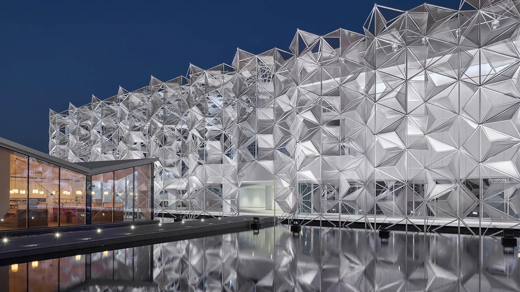
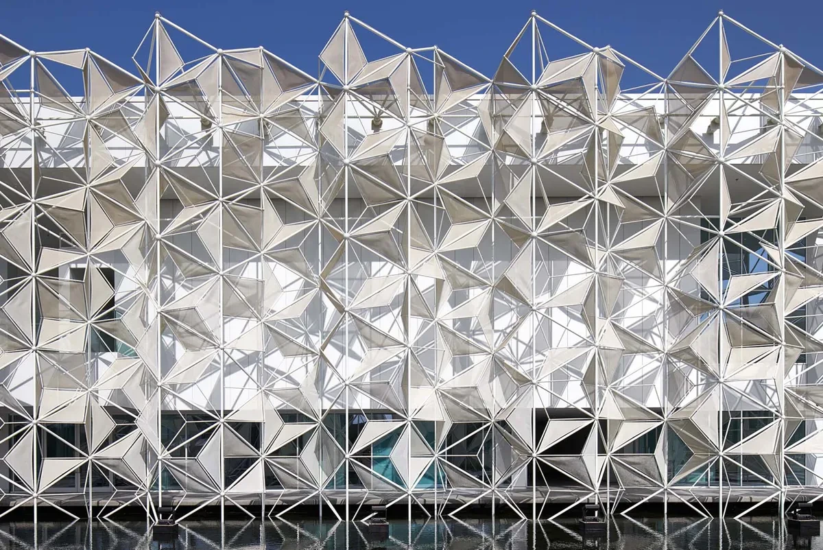
Arup describes the Kumiko-inspired facade as a freestanding folded arrangement. Folding the initially flat pattern reduced the required members relative to a conventional three-dimensional truss and helped produce compact joints. The primary frame, secondary members and scattered triangular membranes have distinct roles. I avoid calling this a timber facade solely because its pattern evokes traditional craft. [5]
Membranes and movement
The engineer describes springs and ropes supporting membranes that can move in wind, alongside early fire simulations. The facade is not a continuous rigid wall. My model abstracts the folded surface and membrane relationships, rather than reproducing the complete pattern or precise joint system. The important mechanism is the relationship between geometry, support, tension and permitted movement. [5]
Verification during assembly
I would begin with verified base positions, erect and restrain the primary framing, add secondary members and install the membranes before coordinated testing. Temporary stability matters before the folded assembly is complete. Membrane tension and clearances need inspection against actual criteria. Water features and visitor access introduce further interfaces that should be completed without damaging the facade.
My professional lesson
Japan provides a useful distinction between cultural pattern and engineering realisation. Performance comes from geometry, materials and detailed connections. I would distinguish a stated reuse intention from evidence of actual recovery. A useful materials record identifies the recovered component, its condition and the requirements of its next use. The same discipline connects fabrication records to construction and future maintenance.
Freestanding folded facade
Structural assembly. Conceptual 3D teaching model; not surveyed geometry or a construction instruction.02 · Construction sequence overview. Follow stages 01–05 below; the same axonometric model is retained throughout.
Five fixed-camera views. Stages illustrate construction relationships; project activities can overlap. Independent SVG/PNG frames and an animated sequence are supplied in the asset package.
Loads and interfaces. Conceptual 3D teaching model; not surveyed geometry or a construction instruction.
Real project photographs and archive material
Completed buildingJapan pavilion: folded facade at night
Capture date not supplied by retrieved source · Native master: 1,840 × 1,035 px
Source: Arup; photographer not identified in retrieved caption
Native source bytes retained; no upscaling or generative alteration.
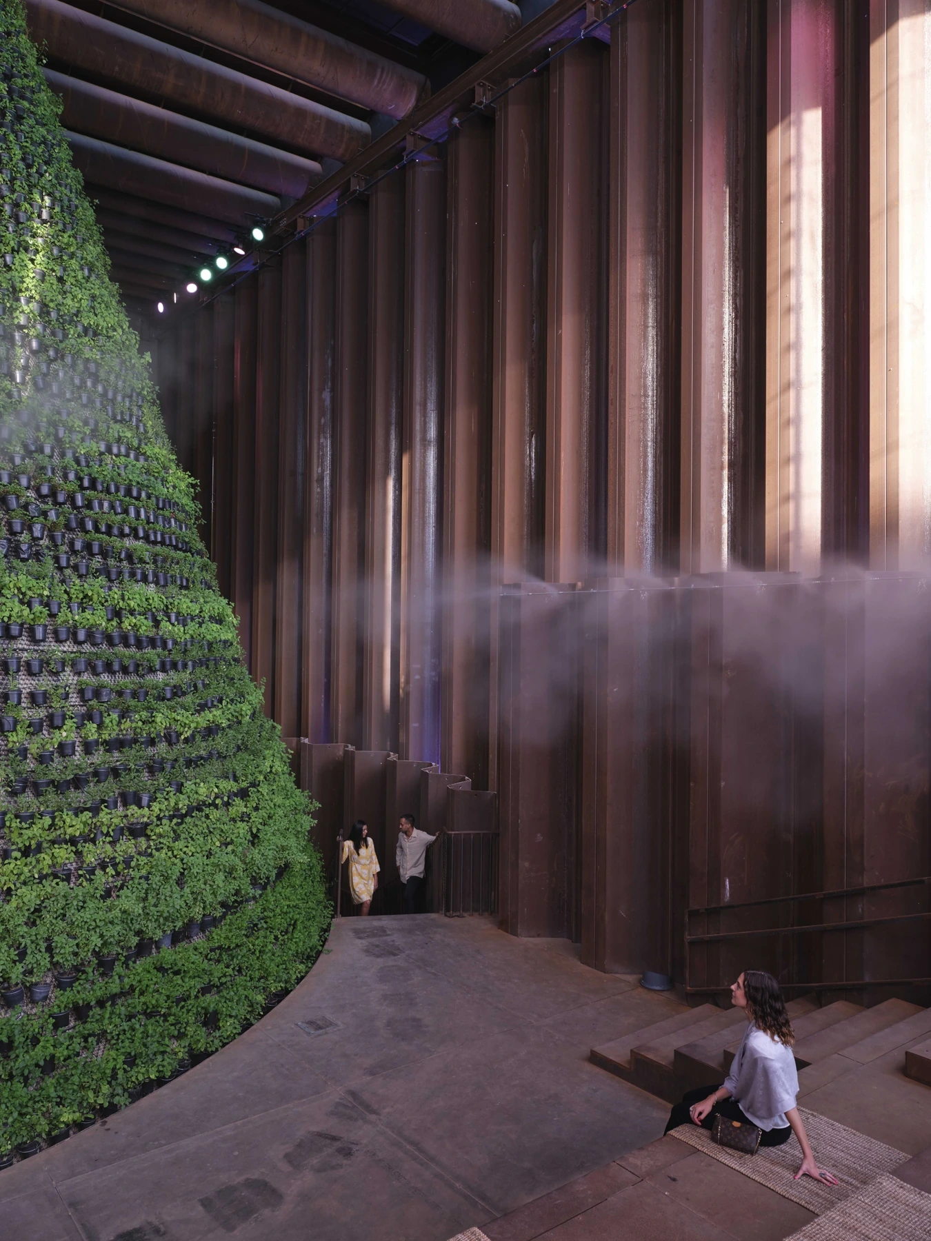
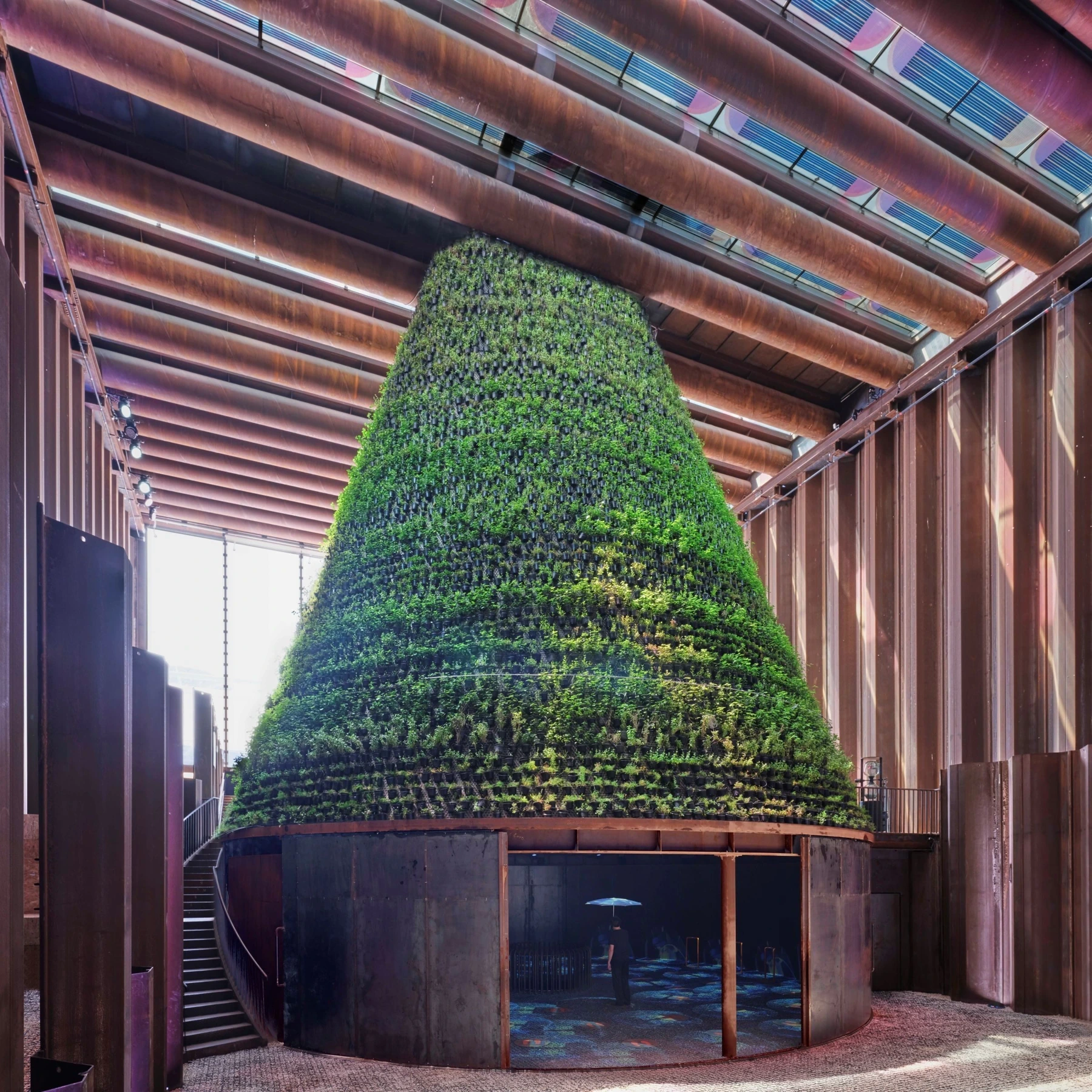
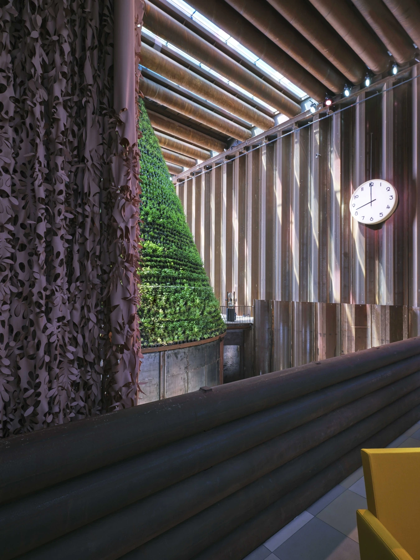
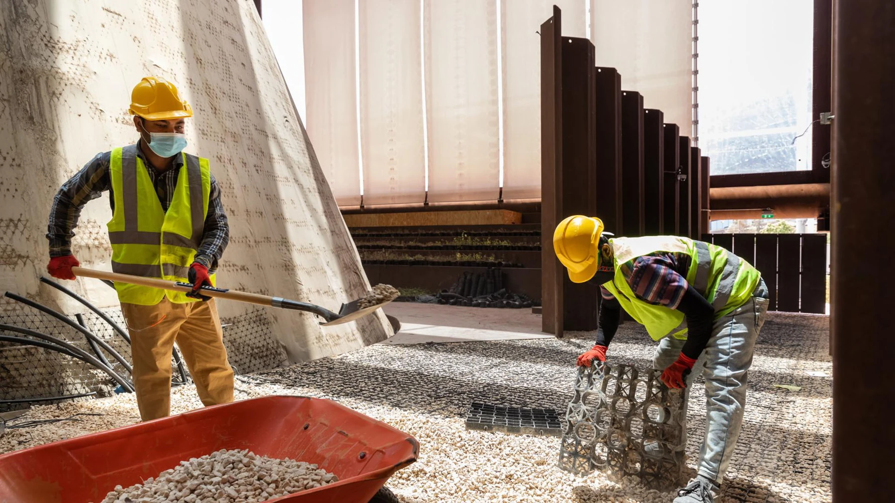
V8 Architects describes a temporary climate system linking water, energy and food. Its main enclosure used locally available steel sheet piles and tubular struts borrowed from Meever, with return to the local construction industry envisaged. I find the use of familiar civil-engineering components valuable: their architectural role changes, while their capacities, connections and handling requirements still need verification. [6]
A concrete-free recovery strategy
Witteveen+Bos reports that no concrete was used, including in the foundations. Double sheet-pile walls incorporated desert sand; the floor used local sand and gravel and rented pavement mats. Its May 2022 publication describes dismantling and planned component returns. This is construction and recovery evidence, while remaining a project-team account rather than an independent audit of every final destination. [10]
Separate frame from environmental exhibit
The steel enclosure and roof should be distinguished from the planted cone, water harvesting and climate systems. The vegetation does not by itself establish a building load path or energy balance. My model shows a recoverable support surface, steel enclosure and interior environmental element. The conceptual stages connect support preparation to assembly and recovery planning, without inventing a concrete foundation.
What I take into procurement
Circular construction is a logistics and ownership strategy with structural consequences. I would record component ownership, connection accessibility, dismantling dependencies and receiving uses before closing the building. Recovery needs inspection, handling and documentation as well as reversible fasteners. The pavilion makes those questions tangible and shows why end-of-use planning belongs near the beginning of a temporary project's programme.
Recoverable steel enclosure
Structural assembly. Conceptual 3D teaching model; not surveyed geometry or a construction instruction.02 · Construction sequence overview. Follow stages 01–05 below; the same axonometric model is retained throughout.
Five fixed-camera views. Stages illustrate construction relationships; project activities can overlap. Independent SVG/PNG frames and an animated sequence are supplied in the asset package.
Loads and interfaces. Conceptual 3D teaching model; not surveyed geometry or a construction instruction.
Real project photographs and archive material
Completed building detailNetherlands pavilion: sheet-pile enclosure and planted cone
Capture date not supplied by retrieved source · Native master: 1,800 × 2,400 px
Jeroen Musch / V8 Architects
Native source bytes retained; no upscaling or generative alteration.
Source and attribution ↗Completed buildingNetherlands pavilion: enclosure and interior environmental element
Capture date not supplied by retrieved source · Native master: 2,400 × 2,400 px
Jeroen Musch / V8 Architects
Native source bytes retained; no upscaling or generative alteration.
Source and attribution ↗Completed building detailNetherlands pavilion: tubular roof members and steel enclosure
Capture date not supplied by retrieved source · Native master: 1,800 × 2,400 px
Jeroen Musch / V8 Architects
Native source bytes retained; no upscaling or generative alteration.
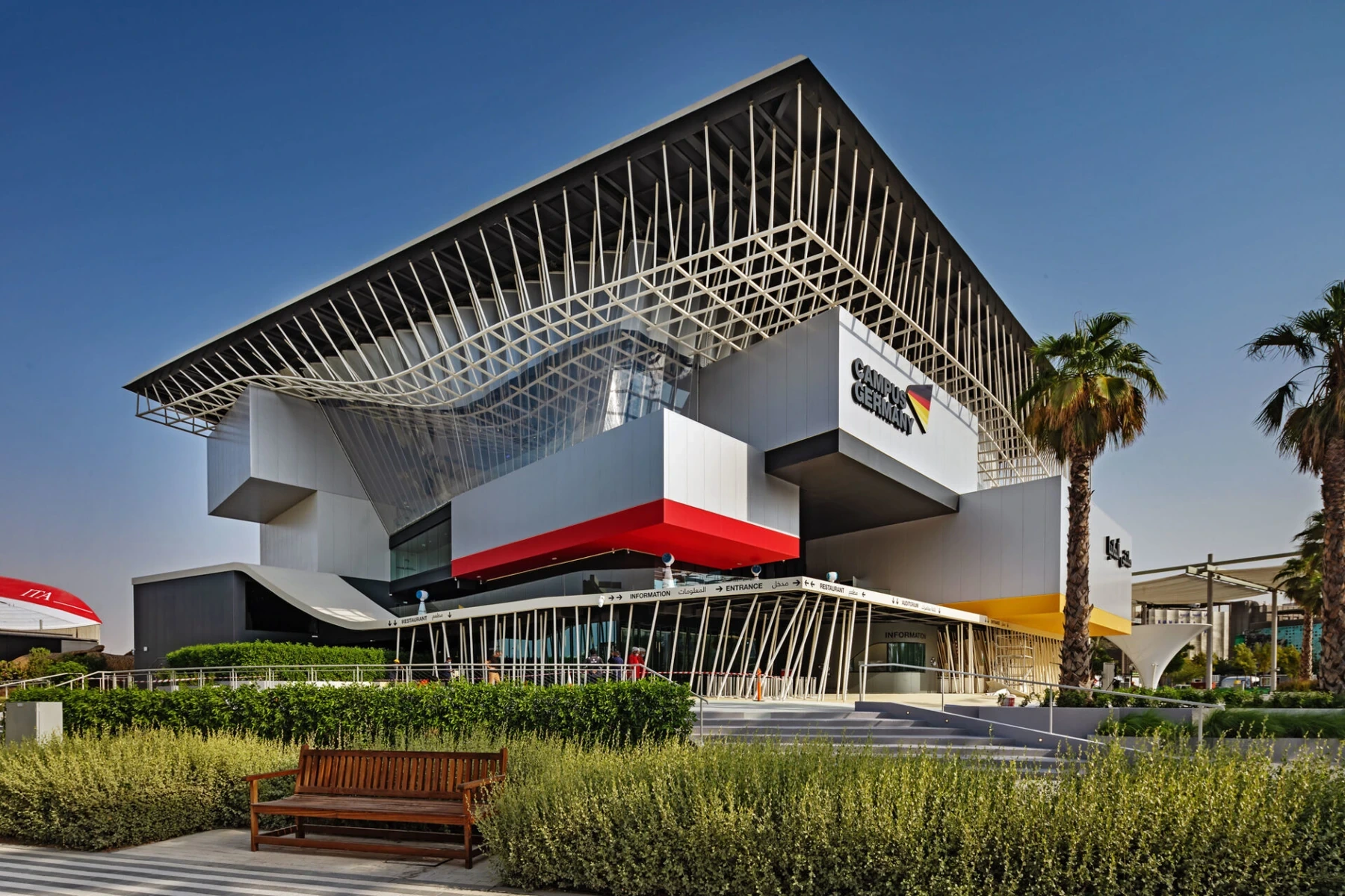
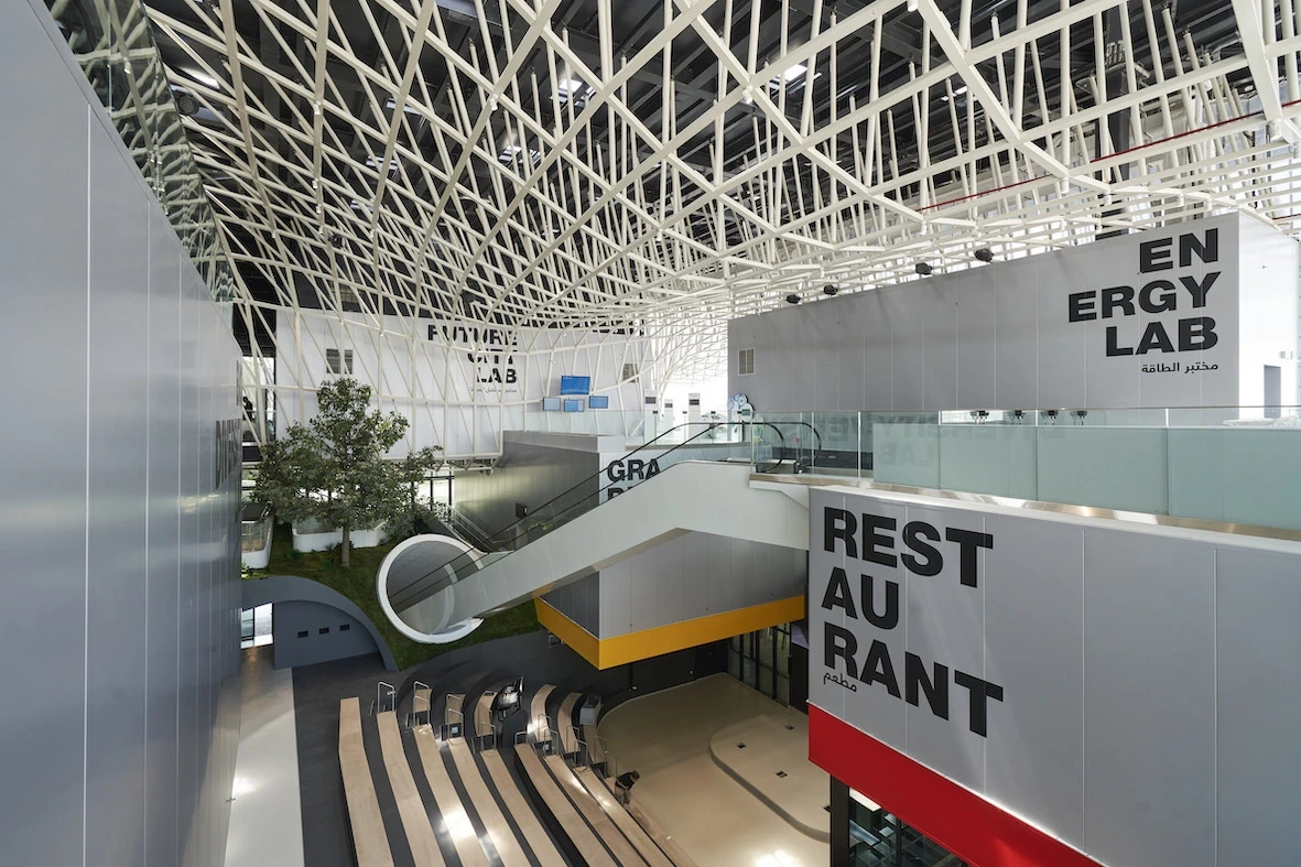
Schlaich bergermann partner describes three concrete cores transferring lateral loads to pad foundations, composite floor slabs and steel trusses within the perimeter walls of the exhibition cubes. The staggered volumes therefore have designed load paths. Primary roof trusses contribute to long cantilevers and the appearance of suspended volumes. I explain the structure through those relationships rather than treating the visible cubes as independent boxes. [7]
Primary roof and lightweight enclosure
The engineer distinguishes the primary roof from a suspended ceiling grid and a lightweight envelope using single-layer ETFE film with prestressed steel cables. The transparent skin does not have the same role as the cores and cube-wall trusses. My model separates the main systems; it does not reproduce every cantilever, truss or the pavilion's exact plan. [7]
A stable condition at every stage
I would develop erection around support completion, restrained wall trusses, floor diaphragms, roof installation and light enclosure. Final stability cannot be assumed during assembly. Each incomplete volume requires a temporary works assessment that accounts for construction loads and the restraint available before neighbouring components connect. Release of temporary support should follow agreed verification, not simply the arrival of the next trade.
My lesson from the pavilion
An apparently complex form can be explained through a small number of structural relationships. A facade can conceal the trusses that make that form possible. For delivery, I want to know where each volume bears, what resists lateral action and when the assembly becomes stable. Those questions turn an architectural impression into an informed discussion of sequence and acceptance.
Cores, wall trusses and roof
Structural assembly. Conceptual 3D teaching model; not surveyed geometry or a construction instruction.02 · Construction sequence overview. Follow stages 01–05 below; the same axonometric model is retained throughout.
Five fixed-camera views. Stages illustrate construction relationships; project activities can overlap. Independent SVG/PNG frames and an animated sequence are supplied in the asset package.
Loads and interfaces. Conceptual 3D teaching model; not surveyed geometry or a construction instruction.
Real project photographs and archive material
Completed buildingGermany pavilion: cores, cubes and roof in the completed building
Capture date not supplied by retrieved source · Native master: 1,920 × 1,280 px
Keller Fotografie / schlaich bergermann partner
Native source bytes retained; no upscaling or generative alteration.
Source and attribution ↗Completed building detailGermany pavilion: interior roof and exhibition volumes
Capture date not supplied by retrieved source · Native master: 1,181 × 787 px
Christian Tschersich / schlaich bergermann partner
Native source bytes retained; no upscaling or generative alteration. Limited-resolution source: use as a supporting image, not a full-screen hero.
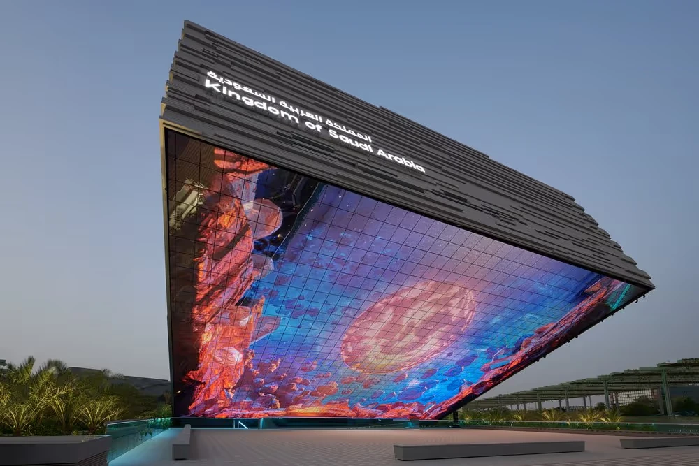
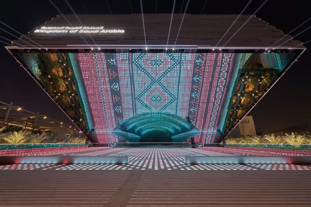
Saudi Arabia: access reveals construction complexity
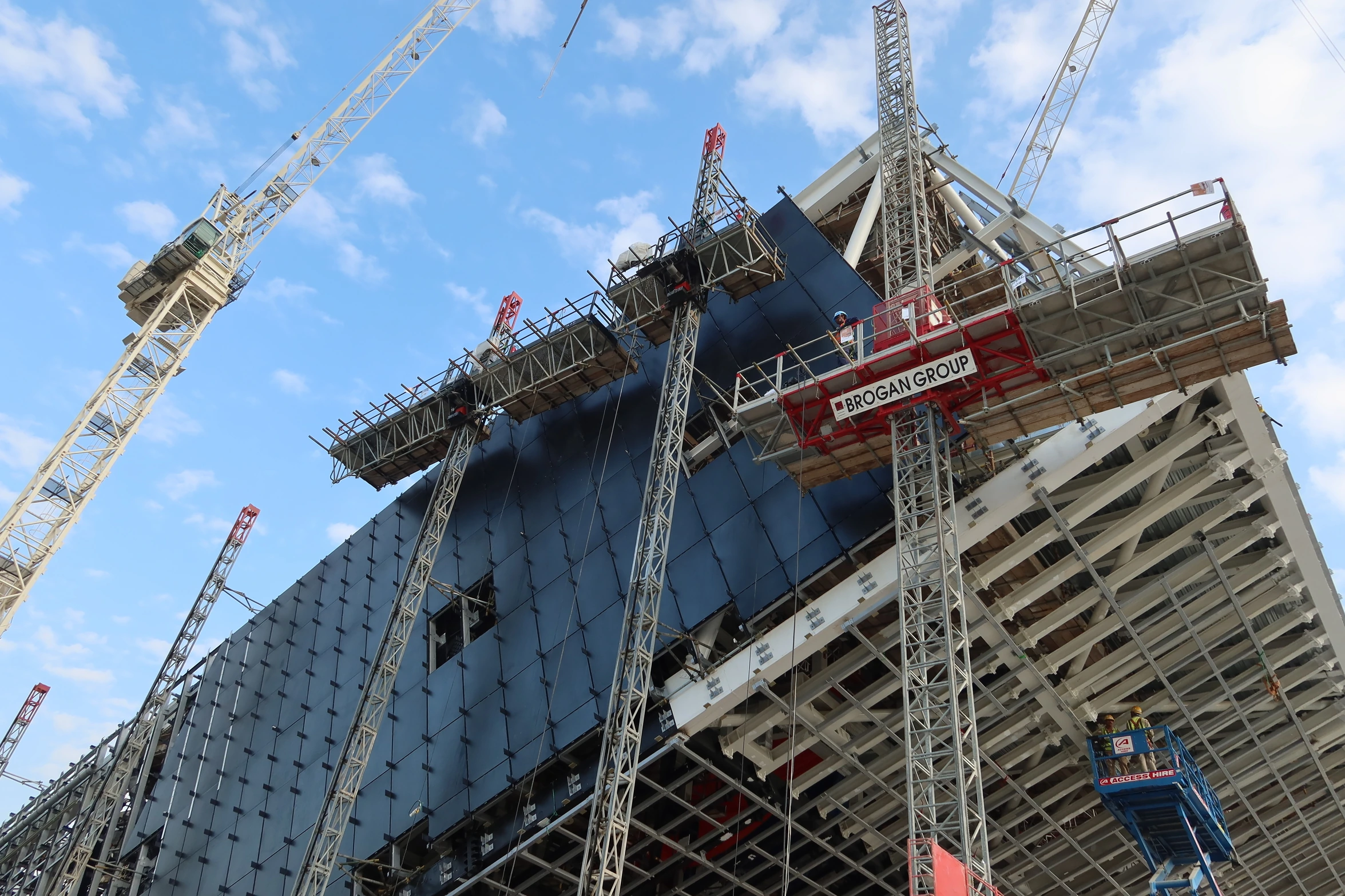
ALEC identifies the pavilion as a design-and-build project integrating structure, facade, services, exhibition fit-out and audiovisual work. Brogan's construction account explains how mast climbers supported installation of brackets, secondary steel, panels and louvres on the north and south elevations. The finished appearance depended on coordination between permanent works and temporary access. [8, 9]
Temporary reactions enter permanent structure
Brogan describes an access platform on steel trusses and additional arrangements where mast ties were difficult. I would verify reactions, ties, permitted construction loads and installation dependencies before releasing that access system. The interface needs a designed load path; manufacturer limitations require an engineered project response. Access planning becomes part of structural coordination, rather than an activity to resolve after the facade team arrives. [9]
A model matched to the available evidence
My Saudi study focuses on a conceptual inclined facade zone, its support and mast-climber access. Public access documentation supports analysis of the installation method more strongly than analysis of every concealed permanent member. The diagram therefore shows preparation, platform and mast installation, facade work and removal. Extending it to a complete pavilion analysis would require the relevant structural drawings and calculations.
What Expo contributes to my practice
Across these six cases, I see permanent stability, temporary support, fabrication control, access, commissioning and recovery as connected responsibilities. My experience of Expo provided the setting for this subsequent research. The useful comparison is how clearly geometry and materials can be translated into a verifiable construction process. I want those relationships to remain understandable to the team that inherits the asset.
Facade installation and temporary access
Structural assembly. Conceptual 3D teaching model; not surveyed geometry or a construction instruction.02 · Construction sequence overview. Follow stages 01–05 below; the same axonometric model is retained throughout.
Five fixed-camera views. Stages illustrate construction relationships; project activities can overlap. Independent SVG/PNG frames and an animated sequence are supplied in the asset package.
Loads and interfaces. Conceptual 3D teaching model; not surveyed geometry or a construction instruction.
Real project photographs and archive material
ConstructionSaudi pavilion: mast-climber access during facade installation
Capture date not supplied by retrieved source · Native master: 2,351 × 1,567 px
Source: Brogan Group; photographer not identified in retrieved caption
Native source bytes retained; no upscaling or generative alteration.